Download Here
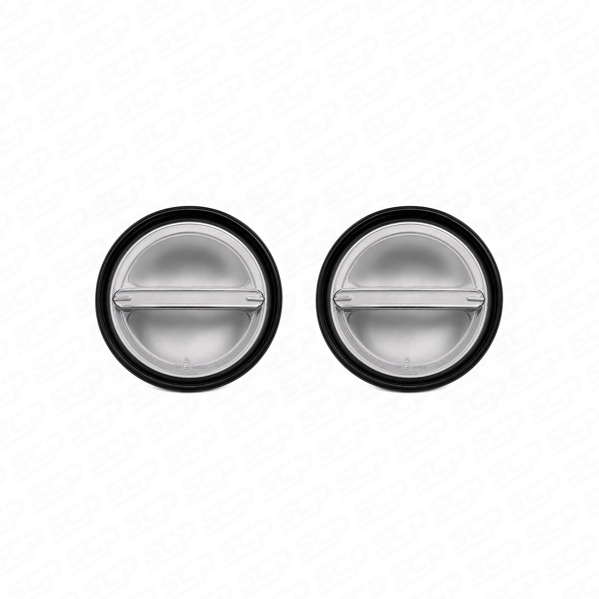
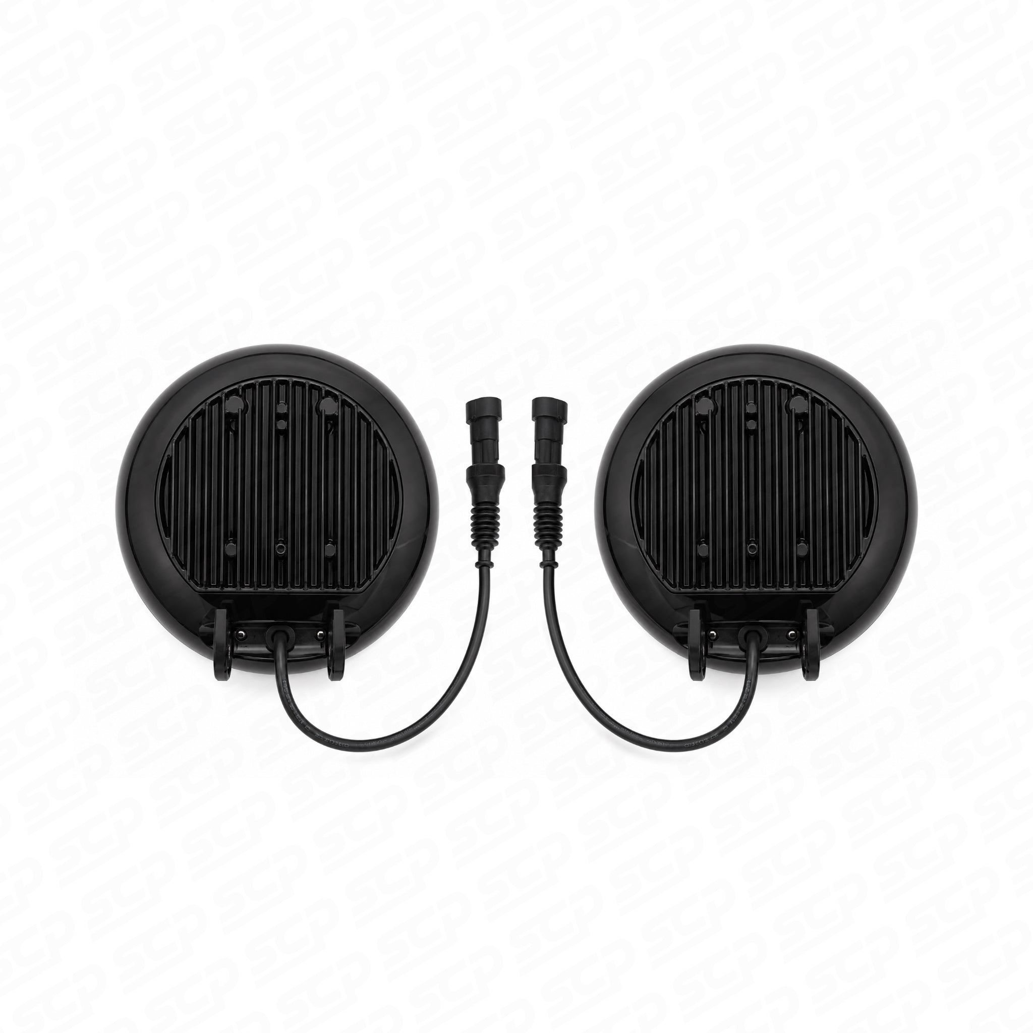
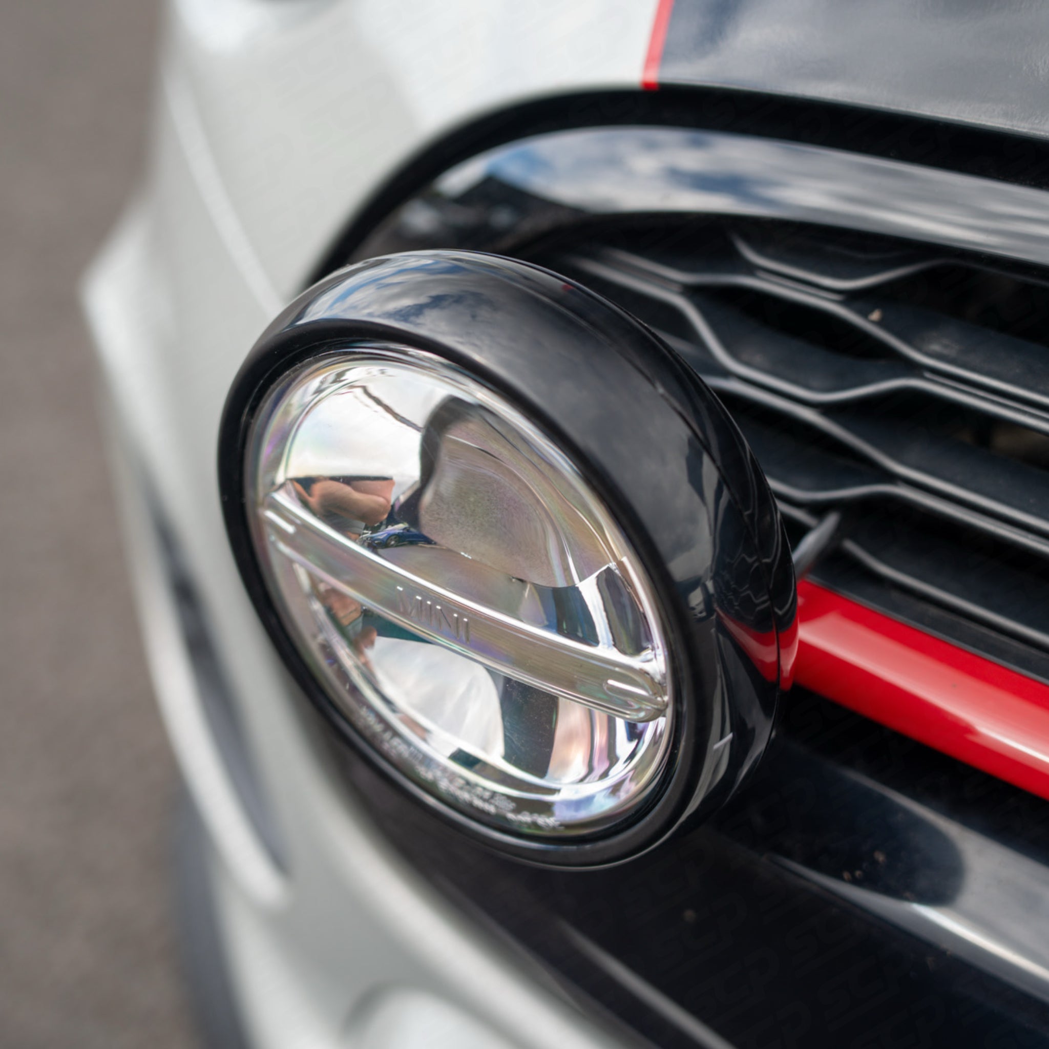
This guide covers the installation of the MINI F55/F56 Auxiliary Rally Spotlight Kit, including the mounting brackets, wiring harness, electrical connections and interior control switch.
Please read through the instructions before beginning installation.
Difficulty: Intermediate
Estimated Installation Time: 2–3 hours
Compatibility: MINI F55 / F56 (subject to grille compatibility)
Tools Required
- Socket set (8mm, 10mm and 13mm)
- T30 Torx screwdriver
- Trim removal tools
- Wire crimping tool
- Cable ties
- Multimeter
Step 1 | Disconnect the Battery
- Open the bonnet and remove the plastic rain tray covering the battery compartment.
- Remove the battery cover by undoing the three 8mm retaining screws.
- Using a 10mm socket, disconnect the negative battery terminal.
- Secure the disconnected cable away from the terminal to prevent accidental contact.
Step 2 | Remove the Centre Grille
- Carefully remove the centre grille from the front bumper.
- Release the existing mounting screws and retaining clips.
- Keep the original screws, as these will be reused when installing the spotlight brackets.
- Ensure the mounting points behind the grille are accessible.
Note: Take care when removing the grille to avoid damaging the surrounding trim or retaining clips.
Step 3 | Install the Mounting Brackets
- Position the left and right spotlight brackets behind the grille opening.
- Align each bracket with the existing vehicle mounting points.
- Secure the brackets using the original mounting screws.
- Ensure both brackets are level and securely positioned.
- Reinstall the centre grille, allowing the mounting tabs to protrude beneath the third grille bar, where applicable.
Note: Bracket positioning may vary depending on the vehicle’s grille design.
Step 4 | Mount the Spotlights
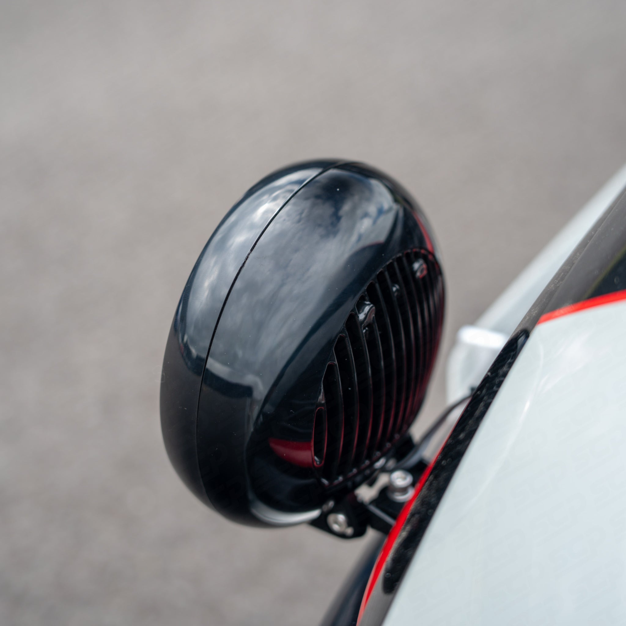
- Attach each spotlight to its corresponding mounting bracket using the supplied hardware.
- Adjust the horizontal position using the base mounting bracket.
- Adjust the vertical position using the side mounting screws.
- Ensure both spotlights are positioned evenly.
Leave the adjustment screws slightly loose until the final beam alignment has been completed.
Step 5 | Install the Wiring Harness
- Route the spotlight wiring behind the front grille.
- Connect both spotlights using the supplied electrical connectors.
- Position the relay in a suitable location within the engine compartment, preferably near the battery.
- Secure the relay and wiring harness using appropriate mounting hardware and cable ties.
- Keep all wiring away from moving components, sharp edges and excessive heat.
Important: Ensure the relay is securely mounted and protected from excessive moisture.
Step 6 | Connect the Electrical Wiring
The supplied wiring harness includes the following connections:
Short Red Wire: Connect to the battery positive (+) terminal through the supplied inline fuse.
Short Black Wire: Connect to the battery negative (-) terminal or a suitable earth point.
Long Red Wire: Connect to an ignition-switched positive (ACC) supply using the piggyback fuse adaptor.
Long Black Wire: Connect to a suitable chassis earth (-) point.
Spotlight Connectors: Connect directly to each spotlight using the supplied connectors.
Ensure the positive battery connection is correctly fused and all negative connections are securely attached to suitable earth points.
Important: Verify the wire functions against the supplied wiring harness before installation. Do not bypass the vehicle’s battery monitoring sensor.
Step 7 | Connect the Piggyback Fuse
- Open the glovebox and remove the fuse box access cover.
- Using a multimeter, identify a suitable ignition-switched (ACC) fuse position.
- Connect the long red ACC wire to the supplied piggyback fuse adaptor.
- Install the original vehicle fuse and a correctly rated additional fuse into their designated positions.
- Insert the adaptor into the selected fuse position, ensuring the correct orientation.
- Secure any excess wiring behind the dashboard.
Important: Fuse positions vary between vehicles. Always verify the selected circuit and avoid connecting to safety-critical electrical systems.
Step 8 | Route and Install the Switch
- Locate a suitable bulkhead grommet between the engine compartment and passenger cabin.
- Carefully feed the switch wiring through the grommet.
- Remove the necessary interior trim panels to route the wiring towards the chosen switch location.
- Position the switch somewhere easily accessible without interfering with vehicle controls.
- Secure the switch using the supplied adhesive or mounting hardware.
- Connect the switch to the wiring harness and tidy any excess wiring.
Note: Ensure the wiring cannot interfere with the pedals, steering column or airbags. Any modified bulkhead grommets must be properly sealed to prevent water ingress.
Step 9 | Test the Spotlights
- Check that all wiring connections are secure and correctly insulated.
- Reconnect the negative battery terminal.
- Switch on the vehicle’s ignition.
- Operate the auxiliary spotlight switch and confirm both lights illuminate.
- Switch the spotlights off and check that they respond correctly.
- Switch off the ignition and confirm that the spotlights cannot remain illuminated.
- Reinstall any removed interior trim panels and covers.
If the spotlights do not illuminate, check the fuse connections, relay, earth points and wiring harness.
Step 10 | Final Checks and Alignment
- Adjust both spotlights to achieve the correct beam alignment.
- Tighten the horizontal and vertical adjustment screws.
- Confirm that both spotlights and mounting brackets are securely attached.
- Check that all wiring is properly secured and protected.
- Ensure the spotlights do not obstruct the vehicle’s original lighting or number plate.
- Complete a final operational check before driving.
Important Installation Information
Vehicle Compatibility
These instructions are intended for the MINI F55 and MINI F56. Mounting positions and installation procedures may vary depending on the vehicle’s specification and grille design.
Electrical Connections
Always verify the wiring configuration, fuse ratings and connection points before installation. The piggyback fuse should only supply the ignition-switched trigger circuit, not the main spotlight power supply.
Road Use
Auxiliary spotlights must be installed and operated in accordance with applicable local road lighting regulations. Additional wiring or controls may be required for road-legal operation.
Professional Installation
We recommend professional installation if you are unfamiliar with automotive electrical systems. Incorrect installation may result in electrical faults or damage to the vehicle.